🚦 Smart Traffic Light System
Smart Arduino Traffic Light Project: build a real-world timed traffic light simulation with pedestrian button controls and state machine Arduino code.
Overview
Traffic lights are a perfect real-world model for learning state machines. Each light (Red, Yellow, Green) represents a state, and transitions happen on a timer, or when a button is pressed.
Technical Insight: This project replicates a real 3-phase traffic sequence (Red-Yellow-Green) which is the absolute standard in 98% of municipal street crossings worldwide. It is the ideal introductory project to learn how industrial state-machine logic controls safety-critical systems.
In simple terms: The traffic light is always in one of four states (Green, Yellow, Red, or Pedestrian Crossing). By writing code that tracks the active state and listens for button interruptions, we build a system that is far more interactive than a simple timer loop.
What you'll learn: Controlling multiple digital pin outputs simultaneously, timed state sequences, push-button input reading, and basic state-machine logic.
Estimated time: 45-60 minutes. Difficulty: ⭐⭐ Easy: a great next step after blinking a single LED.
Components Needed
| Component | Specification | Qty | Notes |
|---|---|---|---|
| Arduino Uno R3 | ATmega328P, 5V | 1 | |
| Red LED | 5mm, 2V 20mA | 1 | |
| Yellow LED | 5mm, 2V 20mA | 1 | |
| Green LED | 5mm, 2V 20mA | 1 | |
| Resistors | 220Ohm | 3 | One per LED |
| Push Button | Momentary SPST | 1 | Pedestrian button |
| Resistor | 10kOhm pull-down | 1 | For button |
| Breadboard + Wires | Standard | 1 |
Component Pin Mapping
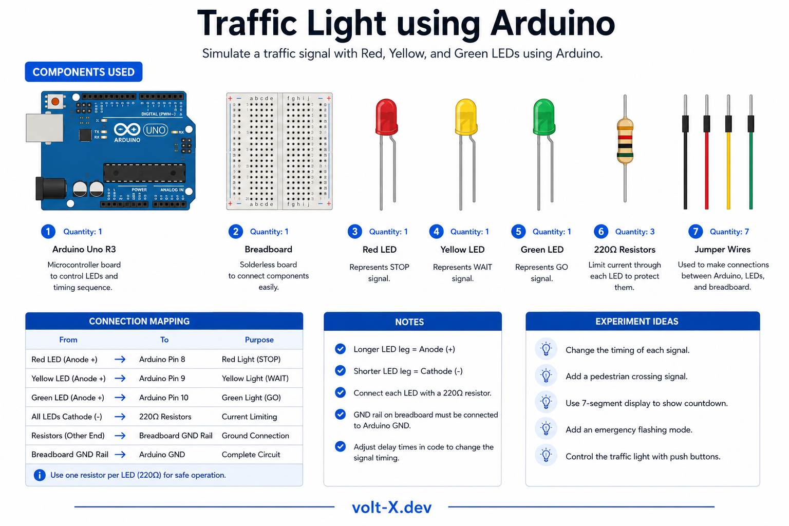
Step-by-Step Tutorial
Place the LEDs
Add Resistors
Connect to Arduino
Add Button
Upload and Test
Arduino Code
// Smart Traffic Light — Volt X
const int RED = 8, YELLOW = 9, GREEN = 10;
const int BUTTON = 2;

void setup() {
  pinMode(RED, OUTPUT);
  pinMode(YELLOW, OUTPUT);
  pinMode(GREEN, OUTPUT);
  pinMode(BUTTON, INPUT);
}

void setLight(int r, int y, int g) {
  digitalWrite(RED, r);
  digitalWrite(YELLOW, y);
  digitalWrite(GREEN, g);
}

void loop() {
  // Green phase
  setLight(LOW, LOW, HIGH);
  for (int i = 0; i < 50; i++) {
    if (digitalRead(BUTTON) == HIGH) break;
    delay(100);
  }
Reviews & Ratings
Sign in to leave a review
Loading reviews...